UM-5 Series Ultrasonic Thickness Gauge:A Precise Instrument For Complex Measurement
General Description
The YUSHI UM-5 Series Ultrasonic Thickness Gauges utilize advanced pulse-echo technology and dual-element transducers to provide accurate, non-destructive measurements by the pulse-reflection method. These ultrasonic metal thickness gauges are designed for a variety of industrial applications including manufacturing quality control, special equipment maintenance and marine/automotive inspection.
An essential instrument for material thickness assessment, the UM-5 series has two specialized models: the UM-5D and the UM-5DL ,they both have thru-coating measurement modes, and the UM-5DL ultrasonic thickness machines are also equipped with data loggers. UM-5 series of colour screen ultrasonic thickness gauges can measure thickness in a wide range of harsh environments and are designed and manufactured in accordance with CE Certificate. The instrument has passed IP67 dust and waterproof test.
UM-5 Principle Elaboration
Ordinary ultrasonic thickness machine adopting the principle of pulse-echo method need to meet the following conditions in order to measure successfully:
1.The first bottom echo must be higher than the gate(the gate level is fixed and cannot be adjusted)
2.There is no other clutter higher than the gate before the first bottom surface echo(otherwise the thickness of the clutter will be measured).
Sometimes,there are many conditions that cannot meet the above requirements,such as severe near-surface corrosion,coarse-grained materials(such as cast iron),aluminum materials,small diameter tubes,ultra-thin plates,rough surfaces,unevenness in the material,internal defects,the laminated structure,etc.
UM-5 series ultrasonic thickness testers can easily solve the above problems:
1.The height of gain and gate can be adjusted to make the first bottom surface echo higher than the gate;
2.The blanking function can invalidate other clutter before the first bottom surface echo.
UM-5 Series Main Function
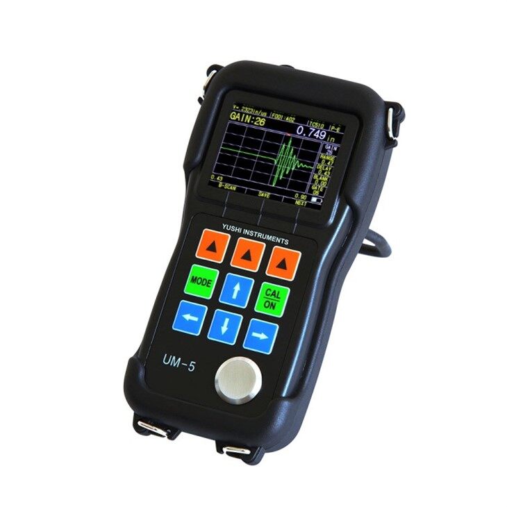
1.Real-time color A-scan
The user can directly see the color ultrasonic signal wave pattern on the screen,which is essential for verifying whether the measured thickness reading is correct or not. In many cases,erroneous thickness readings or even no readings can be caused,the user can can easily find the problem according to the waveform.
2.Adjustable Gate Height
Only when the echo is higher than the gate,the instrument can recognize and receive the echo,and will have a measured value.
3.Red Arrow
There is a red arrow in the A-scan mode to indicate the measuring point,and the thickness reading is the abscissa of this point.It can help judge whether the thickness reading is correct.
4.Gain Adjustment
Adjust the magnification of the echo signal by the instrument,manually increase or decrease in units of 1dB.This function is very effective for the measurement of sound attenuating materials.
5.Blanking Function
Invalidate the waveform in the range of the red blanking bar,and filter out harmful clutter that affects the measurement,such as the noise caused by the rough surface of the material or the internal unevenness.
6.Range
Adjust the range of the waveform displayed on the screen,the waveform is visually compressed or expanded.If the display range is not set correctly,the echo waveform may appear in an invisible area,but the measured value can still be displayed correctly.
7.Delay
Adjust the starting position of the waveform displayed on the screen,the waveform is visually moved horizontally.
8.The function of through coating,without removing the coating
YUSHI is the first in China to launch the thickness gauge with penetration coating technology.UM-5D and UM-5DL also have this widely claimed function.There are more advantages in this mode:
No zero point calibration;
High stability
Zero drift
9.Live Color B-Scan
UM-5 series thickness gauge with live B scan function.Show the cross-sectional view of the workpiece along the movement track of the probe,use for observe the underside contour of the workpiece.
10.Larger memory,more convenient storage function
It can save one hundred thousand thickness values and one thousand A/B-scan waveforms,waveform and thickness value can be mixed stored in the same file.
11.Rectification Mode
Optional RF+,RF-,half+,half-,full wave
RF+ describes the complete echo form;
Rf- indicates the phase waveform of RF+
half + means putting off the half – echo and only left the half + echo;
half – means putting off the half + echo and turn the half – over to +;
full wave indicates the half + echo and the overturned half - echo.
12.More Practical Features
Difference/reduction rate:The difference mode shows the difference between the measured and the preset thickness. Reduction rate is to calculate and display the percentage of thickness loss as the material is thinned,The typical application is to measure metal materials that have been thinned by bending.
Max/Min value capture: Current thickness value, Min and Max thickness values are displayed on the screen at the same time.
Alarm mode:Dynamically change the color of the thickness reading when alarming.
Adjustable update rate 4Hz, 8Hz, 16Hz : select 4Hz for common applications, and select a higher update rate for rapid scanning, such as high temperature measurement.


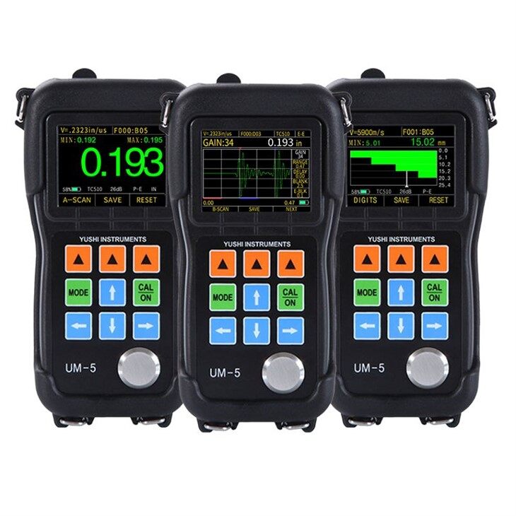
Normal Display Modes of UM-5 Series

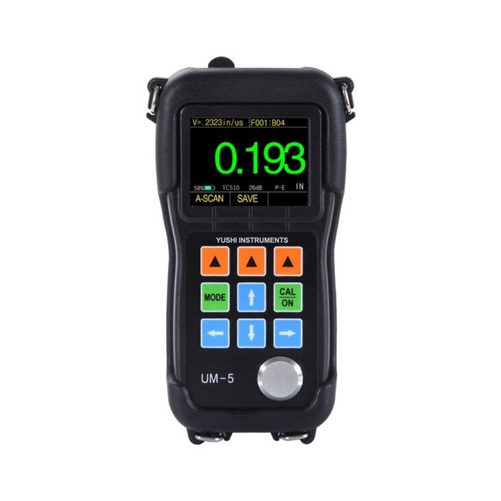
THICKNESS VALUE MODE
The default interface. This interface mainly shows the present thickness value with large digits.
1-the present thickness value ,2-probe types, gain degree, single-echo, measuring units ,3-material velocity ,4-battery power display,5-A-scan interface

DIFFERENCE/RATE-OF-REDUCTION MODE
The interface displays the Difference (the difference between the measured thickness and the nominal thickness) and Reduction (the difference as a percentage of the nominal thickness).
1-the difference between the nominal value and the measured value,2-the ratio between the difference and the nominal value,3-the currently measured thickness value,4-the nominal value,5-difference signal,6-material velocity,7-battery power,8-A-scan interface ,9-probe type, gain degree, single echo, measurement unit

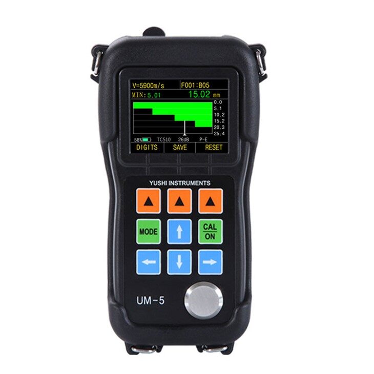
LIMITS VALUE SCANNING MODE
This mode allows the user to catch the real-time maximum and minimum thicknesses when test the thickness of material continuously.
1-the current measured value,2-the maximum value,3-the minimum value,4-unit,5-material velocity,6-battery power,7-A-scan interface,8-rese
The Applications Of UM-5 Series


Differences between UM-5D,UM-5DL
|
Feature |
UM-5D |
UM-5DL |
Data Logger Option |
|
|
Color Display |
√ |
√ |
||
|
Time-based A-scan |
√ |
√ |
||
|
Time-based B-scan |
√ |
√ |
||
|
Control of Gain and Gate |
√ |
√ |
||
|
Blanking |
√ |
√ |
||
|
Thru-painting&coatings |
√ |
√ |
||
|
Data Logger |
× |
√ |
√ |
|
|
Dataview Software |
× |
√ |
√ |
|
The Probes Specification
| Model | PT08 | TC510 | TC550 | ZT12 | PT06 | PT04 | GT12 |
| Type | Standard | Standard Configuration | Composite Elements | Cast Iron | Small Tube | Fingertip | High Temperature |
| Frequency | 5MHz | 5MHz | 5MHz | 2MHz | 7.5MHz | 10MHz | 3MHz |
| Contact Diameter | 10.6mm | 13.1mm | 13.1mm | 17.5mm | 9.1mm | 7.3mm | 14.2mm |
| Measurement Range | 0.8-100.0mm | 1.2-200.0mm | 1.0-200.0mm | 4.0-508.0mm | 0.8-30.0mm | 0.7-12.0mm | 4.0-80.0mm |
| Temperature Range | -10~60℃ | -10~70℃ | -10~70℃ | -10~70℃ | -10~70℃ | -10~70℃ | -20~480℃ |
UM-5 Standard Configuration
|
Name |
Quantity |
|
Main Unit |
1 |
|
Probe |
1 |
|
Probe Cable |
1 |
|
Alkaline Battery |
2(Prohibition of air transport) |
|
Couplant Bottle |
1(Prohibition of air transport) |
|
Carrying Case |
1 |
|
Operating Manual |
1 |
|
USB Cable |
1(Only for UM-5DL) |
|
Software |
1(Only for UM-5DL) |
Optional Configuration
|
High-temperature Probe |
Cast Iron Probe |
|
Small Tube Probe |
Fingertip Probe |
|
Probe Cable |
Stepped Calibration Block |
|
Rubber Sheath |
Storage Option(only UM-5) |
Technical Paraments of UM-5 Series
|
Display Type
|
2.4" color 320 × 240 dot-matrix LCD screen
|
|
Operating Principle
|
Ultrasonic pulse echo and echo- echo method with dual element transducer
|
|
Measuring Range
|
0.5mm to 508mm(0.025" to 20.00"), depending on material, probe and surface condition
|
|
Measuring Resolution
|
Selectable 0.01/0.1mm(0.001"/0.01")
|
|
Measuring Error
|
±0.05mm (H<10mm)
± (0.5%H+0.01)mm (H≥10mm)
Note: H is the thickness of the measured object
|
|
Measuring Limits of Tube (Steel)
|
Φ20mm×3.0mm(PT-08 probe)
Φ15mm×2.0mm(PT-06 probe)
The measuring error is within ±0.1mm
|
|
Units
|
Inch or Millimeter
|
|
Rectify Modes
|
RF+, RF-, HALF+, HALF-, FULL
|
|
Display Mode
|
Thickness Value, Min. / Max. capture, DIFF/RR%, A-Scan, B-Scan
|
|
V-Path Correction
|
Automatic,compensate the non-linearity of dual element probe
|
|
Update Rate
|
Selectable 4Hz, 8Hz, 16Hz
|
|
Material Velocity Range
|
500 to 9999m/s (0.0197 to 0.3937in/us)
|
|
Languages
|
Selectable Chinese, English, Germany, French,Japanese,etc.
|
|
Alarm Settings
|
Minimum and Maximum alarms. Dynamic waveform color change on alarm
|
|
Power supply
|
Two 1.5V AA batteries, 24 hours standby time
|
|
Instrument Shut-off
|
Optional Automatic shutdown or manual shutdown after no operation for 5, 10, or 20 minutes
|
|
Operating Temperature
|
-10°C to +50°C (+10°F to +120°F), special requirements up to -20℃
|
|
Size
|
153mm × 76mm ×37mm(H ×W ×D)
|
|
Weight
|
280g including batteries
|
|
Warranty
|
1 year
|
Probe and Measuring Range
| Probe Type | Frequency(MHz) | Contact Area Diameter | Measuring Range |
Allowable Contact Temperature
|
| Cast Iron Probe ZT-12 | 2 | 17.5mm |
(4.0~508.0)mm
|
(-10~60)℃
|
| Standard Probe PT-08 | 5 | 10.6mm |
(0.8~100.0)mm
|
(-10~60)℃
|
| Standard Probe TC510 | 5 | 13.1mm |
(1.2~200.0)mm
|
(-10~70)℃
|
| Composite Crystal Probe TC550 | 5 | 13.1mm |
(1.2~200.0)mm
|
(-10~70)℃ |
| Small Tube Probe PT-06 | 7.5 | 9.1mm |
(0.8~30.0)mm
|
(-10~60)℃
|
| Miniature Probe PT-04 | 10.5 | 7.3mm |
(0.7~12.0)mm
|
(-10~60)℃
|
| High-Temperature Probe GT-12 | 3 | 14.2mm |
(4.0~80.0)mm
|
480℃ below |


