

Foreword
Ultrasonic Lamb wave (Lamb) inspection is an important method for thin plate inspection. However, due to its low use and complexity, operators often have difficulty implementing it correctly.
In this paper, we will introduce the Lamb wave inspection method from both theoretical and practical aspects, and discuss mode selection and precautions.

In ultrasonic flaw detection of thin plates, ultrasonic Lamb waves are often used for detection because the steel plate is thin and the longitudinal interface wave and bottom wave are difficult to be clearly distinguished.
However, Lamb wave detection is more complicated, and many flaw detectors have doubts on the excitation and wave mode selection. In this paper, we will discuss the mode selection of Lamb wave flaw detection.
The theoretical basis of Lamb wave probing is the dispersion equation. The Lamb wave frequency equation under free boundary conditions is as follows:
Equation (1) is the frequency equation for the symmetric type (S-type):

Equation (2) is the frequency equation for the asymmetric type (A-type):

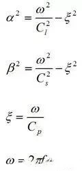
Cl - longitudinal wave velocity in the material in metres per second (m/s);
Cs - transverse wave velocity in the material in metres per second (m/s);
Cp - Lamb wave phase velocity in metres per second (m/s);
t - plate thickness in metres (m);
f - Lamb wave excitation frequency in hertz (Hz).
Selection of Angle of Incidence and Wave Mode
1. With known plate thickness and selected operating frequency, we can determine the phase velocity of the desired mode by referring to the dispersion curve in Figure 1.
2. Mode selection is required due to the different attenuation and reflection characteristics of different Lamb wave modes.
The principle of selection of Ultrasonic Lamb Wave:
1. High signal-to-noise ratio: Strong and clear reflected waves at the end face.
2. Low attenuation and long propagation distance: to improve detection efficiency.
3. Pure excitation wave mode: to avoid the interference of other mode waves in order to judge the defects more accurately (choose the point which is farther away from other mode waves).
4. Low rate of change: to ensure that the wave mode conversion wave caused by defects or end angles is after the main wave, which helps defect judgement.

In the actual flaw detection process, preference should be given to the region where the group velocity curve is relatively flat to ensure that the change of group velocity is small, so that the echo distance remains stable.
The above is the basic method of determining the wave mode through theoretical calculation. However, in actual inspection, the angle of incidence of the Lamb wave probe may differ from the calculated value.
In addition, variations in the thickness of the plate and instability of the probe frequency may excite multiple Lamb wave modes.
At the same time, the presence of defects or boundaries may lead to changes in the wave modes, making the ultrasonic Lamb wave inspection process relatively complex and requiring extensive practical experience.
Precautions for Detection Using the Ultrasonic Lamb Wave Method
(1) It must be confirmed that the waves excited are Lamb waves. Lamb waves are less sensitive to surface oil than surface waves, which are significantly weakened when they encounter oil, while Lamb waves are relatively unaffected by oil during propagation. In addition, the Lamb wave will undergo a mode shift when it encounters the end, which will lead to a change in the echo width when the probe is moved, while the pulse width of the transverse wave echo remains unchanged.
2) It is recommended to use multi-mode detection as much as possible, as a single mode may lead to missed detection in certain areas. It is usually recommended to use at least two wave modes for detection.
3) For delamination defects, the leading edge may be narrower and not produce emission, which may lead to missed detection. However, the delamination phenomenon causes a mode shift, which can be detected by aiding the observation of end reflections.